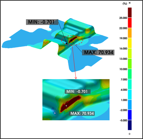
Description:
Unlock precision in sheet metal forming. Learn the limits of the traditional Forming Limit Diagram (FLD) and discover how advanced simulation and failure models provide the accuracy needed for AHSS, complex geometries, and reducing springback.
Introduction
In the high-stakes world of automotive and aerospace manufacturing, the relentless pursuit of lightweighting, complex part geometries, and improved safety standards has driven the adoption of Advanced High-Strength Steels (AHSS) and complex aluminum alloys. For decades, the Forming Limit Diagram (FLD) has been the cornerstone of formability analysis, a trusted guide for predicting necking and splitting in sheet metal stamping. However, as materials become more complex and designs more ambitious, the industry is reaching the boundaries of what this traditional method can accurately predict. The question for today’s simulation engineers is no longer just if a part will fail, but how to precisely predict and prevent failure in ways the conventional FLD cannot.
When the Forming Limit Curve Falls Short
The Forming Limit Curve (FLC), the critical boundary within the FLD, represents the onset of localized necking for a given material under linear strain paths. For a simulation engineer or a tool and die designer, this has been the go-to reference for a simple “pass/fail” assessment. If the strain in the simulated part remains below the curve, the stamping process is considered safe.

FLD Plot: A classic FLD showing the “safe,” “marginal,” and “fail” zones, with simulated strain points plotted for a simple part.
However, this reliance on a simplified model presents significant challenges in modern manufacturing:
- The AHSS Conundrum: Advanced High-Strength Steels exhibit complex hardening behaviors and are highly sensitive to the strain path. The traditional FLC, determined under ideal laboratory conditions with linear strain paths, often fails to accurately predict formability for AHSS in multi-stage forming processes where the strain path is non-linear. This leads to unexpected failures on the shop floor, even when initial simulations predicted a safe process.
- Non-Linear Strain Paths: In complex multi-stage drawing operations, the material is stretched, compressed, and bent in various sequences. The forming limit of the material is not constant; it evolves with the deformation history. A standard FLD cannot account for this evolution, leading to either overly conservative process parameters that increase costs or, worse, unforeseen failures that delay production.
- Beyond Necking—The Rise of New Failure Modes: The FLD is primarily designed to predict necking-induced failures. Modern designs, especially with AHSS, are susceptible to other failure modes that the FLD overlooks, such as:
- Edge Cracking: Cracks initiating from the trimmed edge of the blank, are a common issue not predicted by the standard FLD.
- Shear Fracture: Failure due to high shear stresses, particularly in tight radii or complex features.
From Simple Strain to Complex Damage Mechanics
To overcome the limitations of the FLD, advanced simulation software is moving towards a more sophisticated understanding of material behavior, incorporating continuum damage mechanics. Instead of a simple curve, these models treat material failure as an evolving process.
One of the most powerful advancements in this area is the Generalized Incremental Stress-State Dependent Damage Model (GISSMO). Unlike the FLD, which is purely strain-based, GISSMO and similar models consider the triaxiality (the stress state) and the Lode angle (distinguishing between different shear states) to predict failure.
Here’s why this is a game-changer:
- Path-Dependent Failure: GISSMO accumulates “damage” incrementally throughout the entire forming process. This means it accurately captures the effects of non-linear strain paths. If a material is pre-strained in one operation, the model accounts for this history in predicting its failure limit in the next.
- Predicting Diverse Failure Modes: By considering the full stress state, these advanced models can predict not just necking, but also shear fractures and other complex failure types that are invisible to the FLD.
- Coupled Damage and Plasticity: The most advanced implementations couple the damage model with the material’s plasticity model. This means that as the material accumulates damage, its mechanical properties (like stiffness and strength) are degraded within the simulation. This leads to a much more realistic prediction of how and when the part will ultimately fail.
This approach requires more detailed material characterization upfront but pays massive dividends in terms of predictive accuracy, especially for the challenging materials that are defining the future of manufacturing.
Conclusion
The Forming Limit Diagram has been an invaluable tool, but the demands of modern materials and designs have surpassed its capabilities. To truly innovate and reduce time-to-market, engineers need simulation tools that embrace the complexity of modern materials through advanced, path-dependent failure models and AI-driven process optimization.
The future of stamping simulation lies in predictive accuracy and efficiency—minimizing physical tryouts, reducing material waste, and empowering engineers to design with confidence. It’s time to move beyond the curve.
Ready to see the future of formability analysis? Request a live demo to see Dynaform in action!

