
In this post, we’ll walk you through two useful capabilities of Dynaform 6.1: Blank and Trim Line Development. These tools are transformative for any industry involving sheet metal forming and stamping, including:
- Aerospace
- Automotive & Motorcycle
- Transportation
- Industrial Heavy Machinery
Dynaform 6.1 features a host of distinct, useful modules:
- BSE: Unfold sheet metal geometry, quickly perform blank material cost estimations, and improve blank material usability rate.
- FS: Deep drawing, progressive, and line die stamping simulation – improve cycle times by solving stamping defects prior to constructing tools.
- Blank & Trim Line Developments: Near net shape simulations to predict blank outlines and trim line using an iterative optimization approach.
With all the modules, Dynaform quickly resolves sheet metal stamping challenges.
In case you missed it, Dynaform 6.2 was recently released! Learn more about all the new features in Dynaform 6.2, including newly enhanced capabilities, features, and functions in Tube Forming, Geometry Manager, BSE, Sheet Forming, and more in our walk-through webinar.
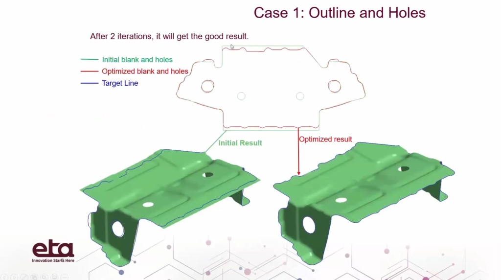
Local blank development to outline holes

Dynaform’s Blank & Trim Line Development module allows you to perform near net shape simulations to predict blank outlines, as well as to outline holes.
In this post, we’re going to use a multi-stage simulation. If you aren’t sure how to perform multi-stage simulations, check out our webinar on Dynaform’s FS module here.
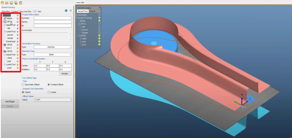
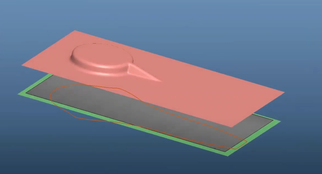
We’ll start with a 3-stage simulation with a blank defined by “Outline,” as seen here:
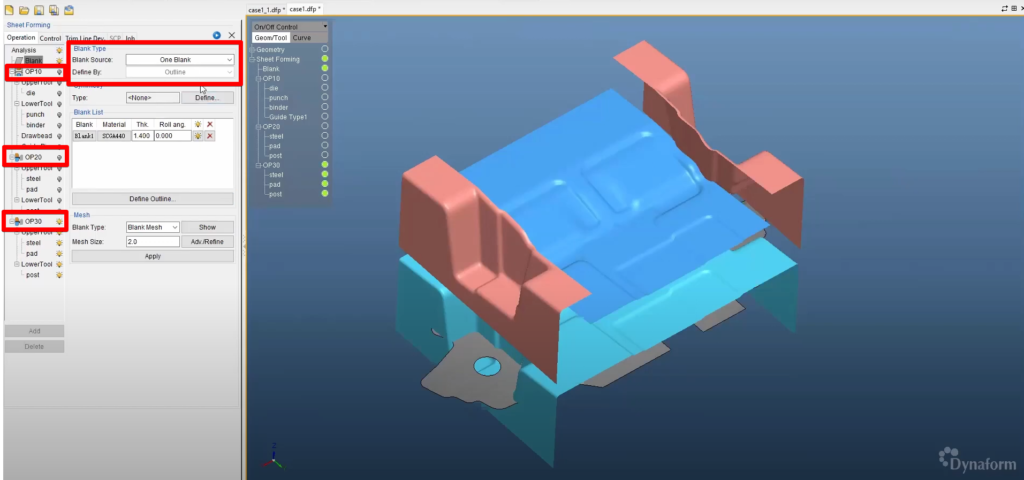
For the first stage, OP10, the center area will be formed, and a little bit on the side. OP20 is our flanging stage. This simulation will form the side flanging areas. For the OP30 stage, we’ll re-strike the side areas to form the flanging areas further.
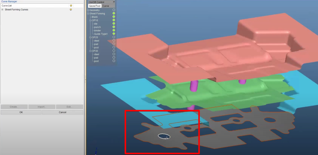
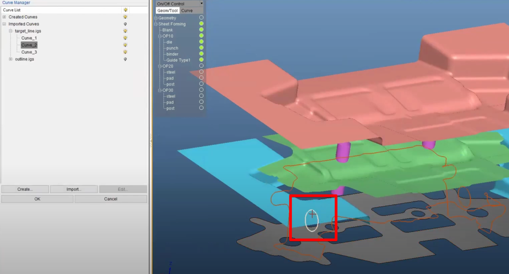
For our simulation, both the outline and the target line were imported to the database. To add the blank outlines and target outlines for a simulation, simply head to the “Trim Line Development” tab and click the “Add” button, then select the outline and target lines:
After selecting the target lines, Dynaform also allows you to select a specific region to optimize if you’d only like to run optimizations on a small segment of the target line. You can use the “Select Local Region” option to define these regions. In our case, we’ll optimize for the entire outline.
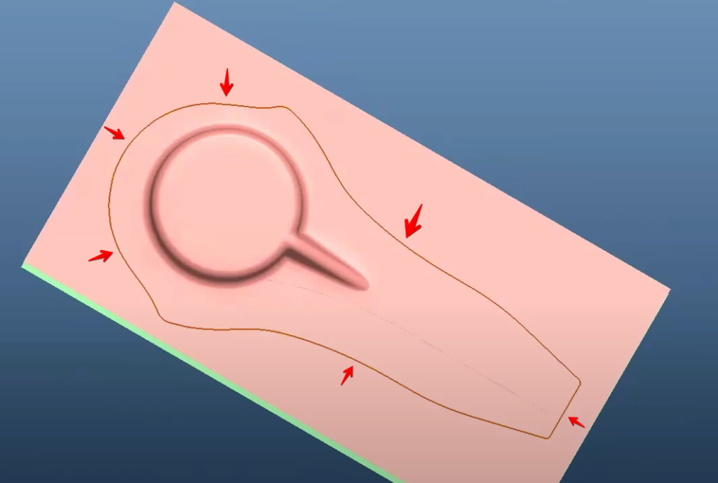
Our outline also has two holes – they’ll need to be added from the Trim Line Development tab as well. To add holes, simply add a new group and select the holes on your outline, followed by selecting the target line.
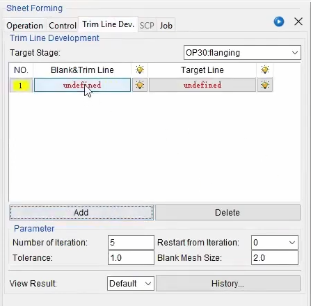
Now we’re finished adding our blank outline, target line, and the holes for both our blank outline and target line. There are, however, a few other options worth highlighting:
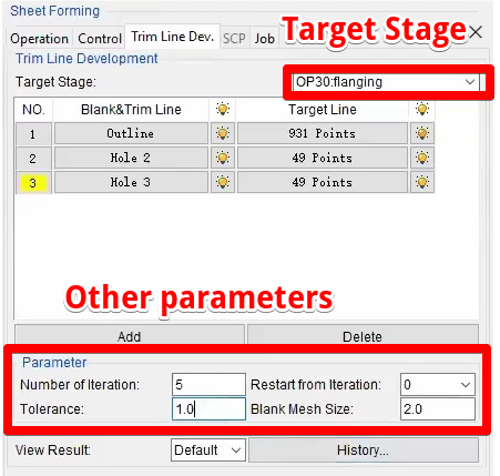
- Target Stage – this option allows you to run your simulations on any stage of your simulation, rather than just the last stage. We’ll use the last stage as our target for this example.
- Tolerance – if the difference between the edge on the final blank with your target line is smaller than the tolerance (in millimeters), the software will consider the simulation as converged and the iterations will cease. If the difference is larger, the software will calculate the compensation and modify the blank outline or trim line again and re-run the simulation from the beginning in an attempt to get closer to the tolerance.
- Number of Iterations – if the simulation is not converged after the number of iterations, the software will cease further iterations regardless of convergence.
- Restart from Iteration – if you only finish 2 iterations, for example, but you’d like to check the results before the simulation finishes, you can set which iteration you’d like to restart from once you continue.
- Blank Mesh Size – after each iteration, when the software modifies the trim line or blank outline, you can set what size you’d like to remesh the blank.
Now let’s run the simulation! A simulation like this typically takes less than 2 hours to finish. This of course depends on the number of elements and their sizes; however, Dynaform’s module saves hours (or sometimes days) of work modifying trim lines and re-running simulations.
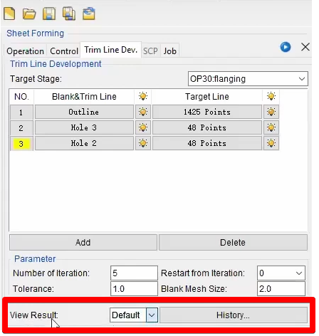
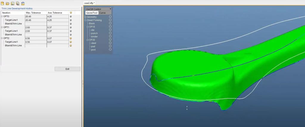
Once the simulation is finished, you can select which stage of the simulation you’d like to view with the “View Result” dropdown – we’ll use “Default” for our example. Now we can click the “History” button, which will load and bring all the iterations from the optimization to the software.
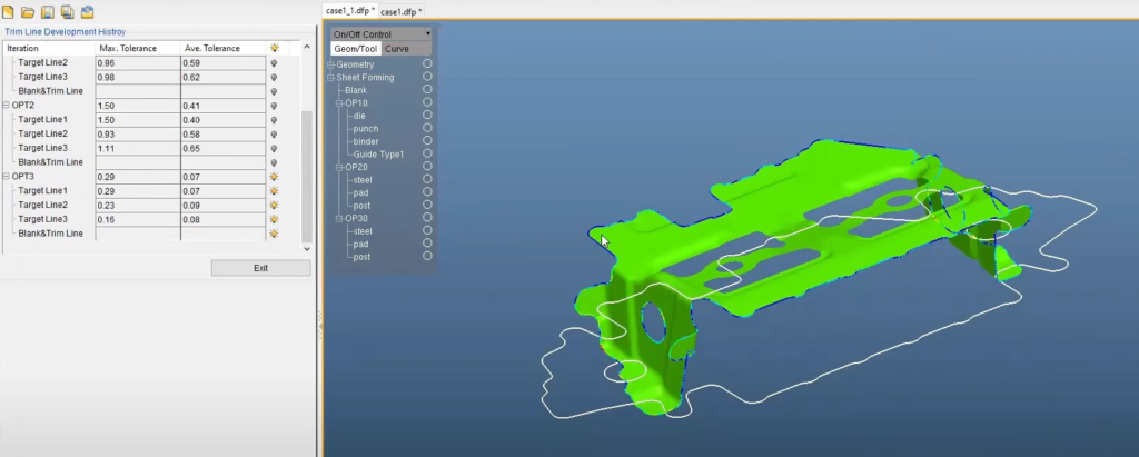
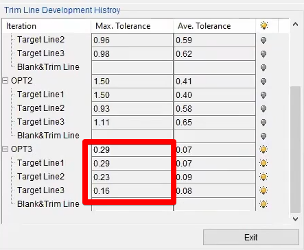
The last iteration of the simulation will show by default. In our case, we reached convergence in our third stage.
Note: These iterations and optimizations are completely automatic.
You can also view the steps of the simulation before reaching convergence by de-selecting the current stage, and selecting the other stages. This allows you to see the deviations from the target line during each stage of the simulation:
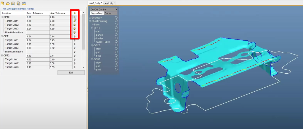
As stated before, the simulations will continue running until the maximum tolerance goes below the tolerance set for the simulation. You can see the tolerance values for each stage of the simulation, as well as for each target line, in the table to the left:
Our simulation is now complete!
Local trim line development of multi-stage optimization
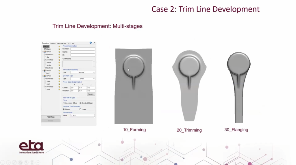
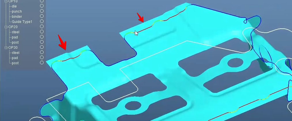
In this simulation, we’ll focus on local trim line developments rather than the blank outline – and similar to the previous example, we’ll have three operations: OP10, OP20, and OP30.
The OP10 operation is a simple forming operation:
OP20 is a trimming stage, so we’ll be using the trim line in the example below to trim the blank:
The OP30 operation will perform a re-strike to flange the vertical wall on this part:
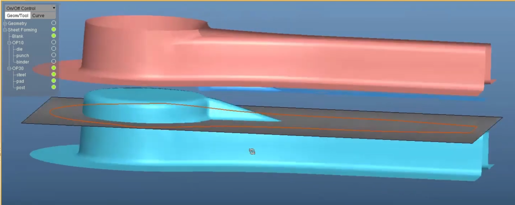
Defining the trim line is very simple. You can pick out the trim line from the trimming stage (in our case, OP20), and pick out the target line from the database:
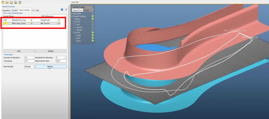
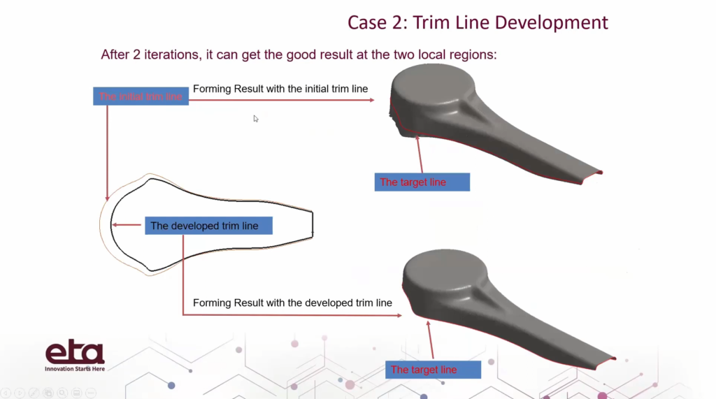
We can view the result of this simulation by clicking History – the exact same process as the previous example. Our simulation managed to reach convergence in OPT2.
Just like before, the software will continue running iterations automatically until convergence is reached!
…
In summary, Dynaform is extremely useful in optimizing initial blank outlines – even with holes – to match target lines, and the software does this automatically. You can get perfect fits with your target lines.
Q&A:
- If you plan on adding guides or pins to locate blanks, will the pins be automatically positioned if the blank is being optimized?
- In the old version, this isn’t the case. After you pick a point on the blank and guide pins, and after the software modifies the trim line or blank outline, the pin will be updated based on the new position automatically.
- Can the blank mesh adapt in the optimization if you have a refined edge in the FS setup?
- Yes. Adaptive meshes are supported in the optimization.
- What is the usual number of iterations required in blank and trim line development?
- Normally, it will converge within 3-4 iterations. If it’s more than this, you’d need to check the model to ensure everything is correct. For most cases, the software can easily converge within 3 iterations.
- What is the lowest range of accuracy?
- Millimeter. Normally we use 1mm, but you can use smaller ones. It’s more difficult to achieve convergence with smaller tolerance, but you have control.